南極地球物理学ノート No. 17 (2012.08.30)
DORISその2:DORIS ビーコンの取り付け測量
澁谷和雄・土井浩一郎・青山雄一
Keyword: 偏心測量, antenna offset, Starec 型アンテナ, Alcatel 型アンテナ, DORIS 網, SYPB
DORISは衛星軌道の精密決定を経て地表の(主に海面の)レーダー高度計高さの精密化を図るだけではなく、発振アンテナの地球中心座標系における3次元位置を高精度で(今では約1 cm精度で)求めることが出来る。これはとりもなおさず、1ヶ月データ位置の長時間(例えば5年)時系列を作るとプレート運動が示せることを意味する。但し、そのためにはアンテナ中心(Starec型 beacon antennaの場合、赤いリングマークの中心:antenna reference point と呼ぶ)が地面に対して動かない(時間変化しない)ことが必要である。また、このような時系列は当然ながらGPSアンテナ参照点やVLBIアンテナ参照点からも得られるので、地球中心座標系でこれらの各参照点が一致するのか、あるいは系統的にずれているのか知るためには、地上測量によりその相対位置ベクトルを各成分1-2 mm精度で求めておく必要がある。このような相対位置(偏心していると呼ぶ)測量は要求される精度から、ふつう古典的な測距儀・測角儀を用いた方法によることが多い(数100 m以内の近距離の場合、一番測量精度が良いとされている)。このような測量を偏心測量あるいは取り付け測量(local tie)と呼んでいる。
1. SYOBの取り付け測量
第34次隊によるSYOB定常運用開始は1993年1月末から2月初旬にかけてであったが、この時期、熟練した国土地理院の測量士は既に基地作業を終えていて、具体的な取り付けは第35次夏隊に持ち越した。SYOB(図1のD点)からのSYOW点(同じくG点)の偏心測量は池田尚應隊員(国土地理院)が1994年1月28日に実施した。ここでSYOWとは第23次隊が設置した16番目の基準点No. 23-16でSCAR GPS campaignに使用されていたmarkerである。D点は図1に示す赤い環状リングマークQの中心で、アンテナが直立していれば、その直下足元にある図2の気泡レベルの鉛直線上方に位置する。この古典的な測量の詳細は省くが、測量士が定められた作業手順、基準点測量・作業規程記載要領(国土地理院)に従って行うもので、特殊な事情がない限り、結果の信頼性には疑いがない(取り付け偏心ベクトルの各成分は3 mm誤差以内に収まる)。この時のDG (= SYOW-SYOB) ベクトルは
DG(1994) = (-316. 322 m, 62.323 m, -73. 692 m) (1)
であった。
その後、再測の機会がなかなか得られなかったが、第39次夏隊の岩田昭雄隊員(国土地理院)が1998年1月28日に再測定を行っている。1998年に得られた結果は
DG(1998) = (-316. 347 m, 62.296 m, -73. 641 m) (2)
で、両式の差ベクトルは
Difference = DG(1998) - DG(1994) = (-25 mm, -27 mm, 51 mm) (3)
であった。明らかにZ成分の偏差が大きくX, Y成分も1 cm以内には収まらなかったが、下記が「特殊事情」である。
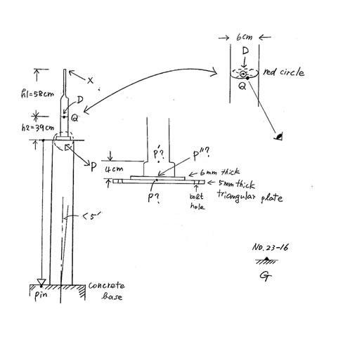 |
図1:SYOBはパイロンタワー上にあり、地上測量基準点から視準するには数cmのあいまいさが残った。 |
第35次隊では図1においてビーコンの根元P(丸囲いの点線)を視準したが、P”なのかP'なのかは判然としなかった。そこで、設計図面から得られる h1 = 4 cm, h2 = 39 cmを用いた∆h = 35 cmでマーカーまでの高さ補正を行った。一方、第39次隊では直接Qを視準したが、ビーコンの太さ(差し渡し直径)は6 cmあるので、当然ながらQ = Dではない。しかも、ステーの張りは結局、目分量であり、経年変化で風下側に傾いていた。ということで、(3)式の差には測量誤差と、経年的なタワーの傾きが生み出した変位による両方の誤差が含まれている。この事情は1998年7月30日付けのFAXでAlain Orsoni宛て送信した。
なお、1995年には昭和基地にもDorne Margolin T型のアンテナによるGPS常時受信ピラーが完成し(別ノートで記載予定)、すべての基準点マーカーの偏心ベクトルは常設GPSのantenna reference point (SYOG) を起点に表現することにしている。SYOWのSYOGからの偏差ベクトルは別の取り付け測量により、
SYOG - SYOW = (25.240 m, -46.394 m, -12.197 m) (4)
であったので、1994年のSYOBについて
SYOG - SYOB = (-291.082 m, 15.929 m, -85.889 m) (5)
ということになる。
2.
SYPBの取り付け測量
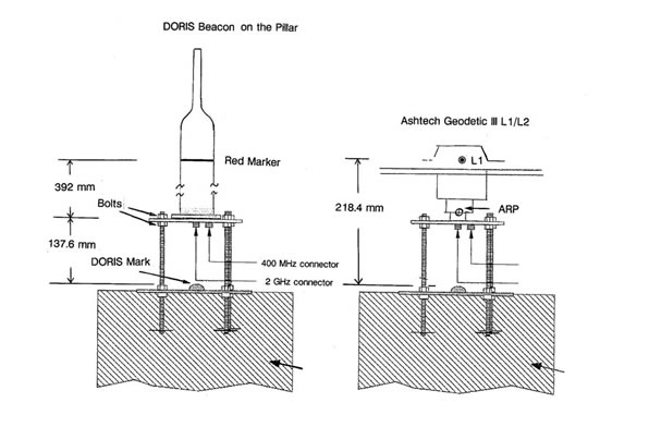
SYPBはコンクリートピラーに固定され、brass disk marker上方には測量用のGPSを固定する台座が組み込まれている(図2)。従ってSYOBと異なり、偏心測量は容易である。図2aのDORISアンテナを一時的に取り外し、図2bのAshtech Gedetic III L1/L2アンテナに置き換えてSYOGからの偏差ベクトルを求め、brass disk からのARP高さ108.4 mmを補正してdisk の座標を求め、DORISアンテナを元の位置に戻した時の赤リングの高さ137.6 mm + 392 mm = 529.6 mmを加えてやれば、赤リング中心DのSYOGからの偏心ベクトルを求めることが出来る。この測定はAshtech Z-FX受信機を用いて1999年5月と8月に第40次隊・福崎順洋隊員(国土地理院)が実施した。2回の測定の不一致度はx, z成分が0 mm, y成分が1 mmであった。結局、得られた結果は
SYOG - SYPB = (-298.055 m, 23.376 m, -89.987 m) (6)
であった。この結果は1999年11月4日、Hervé Fagard宛て送信した。
http://ids.cls.fr/print/doris/stations/station.php3?code=SYPB のsite information (2007/07/12 download) には上記の結果が正しく記載されている。
なお、brass diskからAshtech Geodetic IIIのL1位相中心までの高さ218.4 mmを用いた偏心結果(-297.909 m, 23.497 m, -90.481 m)を誤って記載した報告もあるが、これは誤りである。
 |
|
図2a |
図2b |
| 図2:(a) DORISピラー上のSYPBマーカー位置は0.1 mm単位まで計測した(できた)。(b) GPSアンテナのL1位相中心とARPの高さの差は110 mmだった。従って、ARPはbrass disk markからは108.4 mm上に位置したことになる。 | |
Q and A
Q1: アンテナが安定していること、位置を変更した場合は、前の位置との差が詳しく判っていた方が良いことは判りますが、1 cm精度あれば十分ではないですか?
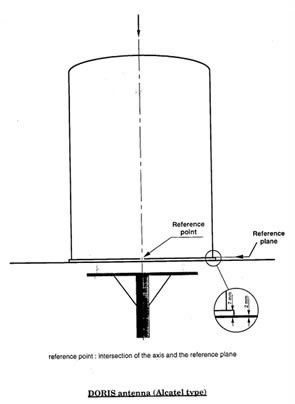
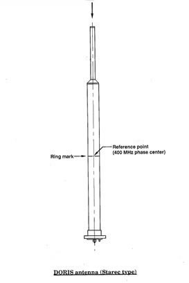
A1: DORIS運用の開始当初(1990年代前半)においては、1 cm精度あれば良かったと思います。しかし、Topex/Poseidon, Jason-1など精度のよいレーダー高度計搭載衛星がどんどん飛び始めると、要求される軌道決定精度が上がり、それに伴って、DORISビーコンの位置決定精度と安定性の要求も上がりました。IGN/CLSはアンテナ位相中心があいまいな、当初のAlcatel型(図3a)アンテナをやめてStarec型(図3b)への切り替えを2000年から2001年にかけて、特に南大洋の小島のDORIS局を中心に、集中的に実施しています(昭和基地では最初からStarec型でした)。そのような更新情報はDORISMail messageというグループメールで関係者に配布されたのですが、そのグループメールから南大洋から南極にかけての維持活動をpickupすると表1のようなログ(地点名・位置は図4参照)にまとめられます。
 |
 |
| 図3a | 図3b |
| 図3:SIMBはDORIS網のアンテナをAlcatel型(左のa)からStarec型(右のb)へ順次交換して行った。昭和基地は1993年の設置当初からStarec型である。 | |
表1 DORIS地上局ビーコンの更新情報 (Information slightly abbreviated/modified) |
||
|---|---|---|
Mail No. |
Date |
Information |
| 0114 |
28-DEC-2000 |
DORIS at Amsterdam Island is out of vertical by a few cm. Replacement is planned for next April. |
0117 |
15-FEB-2001 |
DORIS Starec antenna at Rio Grande has been moved to a new support in order to improve its stability. The antenna was out of vertical to several cm toward North. |
0121 |
21-MAR-2001 |
The stability of the DORIS antenna at Santiago has been improved, by replacing the current guyed 2 m tower (transmission until Feb. 20) with a very rigid, 45 cm sided, triangular metal tower (transmission after Feb. 28). |
0122 |
21-MAR-2001 |
The old Alcatel antenna at Easter Island has been replaced with a Starec one installed on a new support metal tower. Old antenna stopped on Feb. 23, and resumed on Feb. 26 from a new antenna. |
0128 |
23-MAY-2001 |
The corroded supporting plate of the DORIS antenna at Amsterdam Island was changed on March 28, with a new plate of high quality stainless steel. A new Starec antenna was installed. |
0129 |
23-MAY-2001 |
The DORIS Starec antenna at Kerguelen has been moved to a new support in order to improve its stability. Transmission at former position stopped on April 1, and resumed on April 4 from a new location. |
0134 |
19-JUL-2001 |
On 23 June 2001, a major earthquake with M = 8.4 occurred near the coast of Peru. The DORIS antenna at Arequipa (190 km east from the epicenter) showed a displacement of about 30 cm. |
0137 |
06-AUG-2001 |
A new DORIS station has been installed in Mahe (Seychelles). This is located about 300 m from the tide gauge (GLOSS station #273, “Point Larue”), and 5.8 km from the IGS station SEY1. It consists of a version 1.1 beacon and a Starec antenna |
0146 |
07-DEC-2001 |
The DORIS Alcatel antenna at Arequipa, installed 12 years ago, has been replaced with a Starec antenna, installed on a concrete pillar. Transmission at former site stopped on November 20, and resumed from the new site on November 21. |
0158 |
09-JAN-2002 |
The current support of the Starec antenna at Chatham (NZ) has been replaced with a more rigid tower. Before removal of the old support, the centering of the antenna was checked. Corrosion of the aluminum supporting plate had caused a small tilt of the antenna to (2.9 mmE and 0.5 mmN) for the 400 MHz phase center, and (5.6 mmE and 0.5 mmN) for the 2 GHz phase center from the ground. The station will be used by the onboard navigator (DIODE) of the new DORIS instrument on Jason-1. |
0282 |
19-DEC-2003 |
The DORIS station at Yaragadee, initially installed in 1992 and already upgraded with a Starec antenna in 1999, has been renovated again. This renovation consisted in moving the antenna to a new support in order to improve its long term stability without any change of the type of equipment. Transmission from the former position (YARB) stopped on November 27, and resumed on the same day from the new position (YASB). |
0299 |
05-FEB-2004 |
A new DORIS station has been installed at Crozet Island. The DORIS equipment consists of a third generation beacon and a Starec antenna. |
0306 |
05-MAR-2004 |
A new DORIS station has been installed at the “General Belgrano” Argentine base in Antarctica. At almost 78 degrees South latitude, this is the southernmost DORIS station ever installed (on an outcrop). The DORIS equipment consists of a second generation beacon and a Starec antenna. Transmission started on February 6, 2004. |
この表で判る通り、0.5 mm - 1.0 mmの安定性を真剣に求めています。
なお、DORIS網発展の概要が下記文献にまとめられています。
Fagard, H., 2006. Twenty years of evolution for the DORIS permanent network: from its
initial deployment to its renovation. J. Geod., 80(8-11), 429-456.
そしてこの論文のFig. 29(下記図4に再録)が示すようにSYPBはネットワークのrenovation前から最高に近い安定性を示しています。
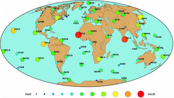 |
図4 |